Features of progecad 2018 professional

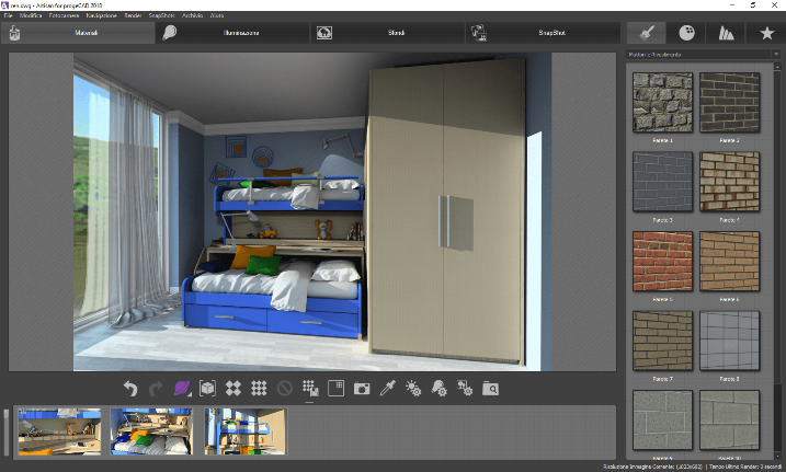
New Advanced Render - Artisan
This is an ideal product for architects and for all those designers who need to view their own drawings in a photorealistically visualization.
progeCAD professional includes the advanced Rendering function, based on the ray-tracing algorithm, new integration with Artisan Renderer. It allows you to create a photorealistic image of your model quickly using a wide range of pre-set materials and lighting setups combined with the ability to create custom lights and realistic materials.
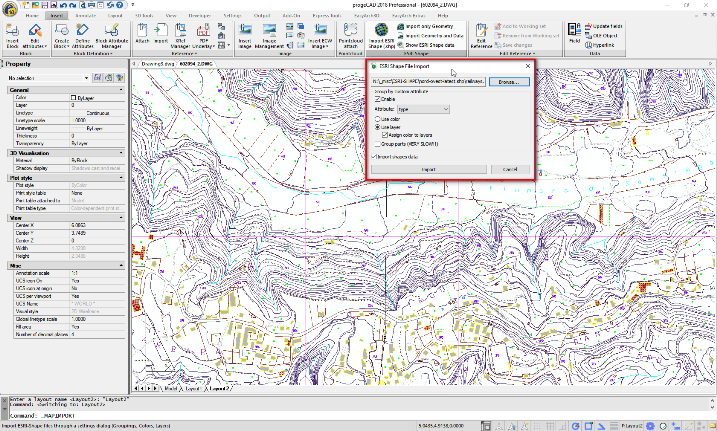
ESRI-SHAPE Import
Import SHAPE (ESRI) files with geometry and its attributes into DWG drawings. Specific commands allow geometry insertion, colours and layers management, data dynamic control.
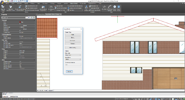
Superhatch Command
Create hatch patterns from images, blocks, external references (xrefs) and wipeouts. Superhatch is an express tools function that lets you quickly hatch with your own pattern, no programming or creation of pat files needed. progeCAD's hatch with image capability is a part of the Superhatch function.
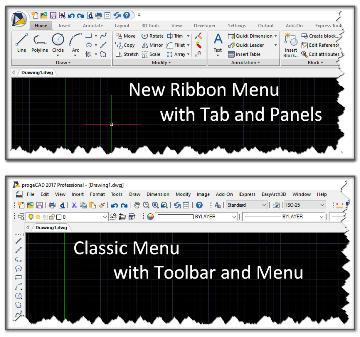
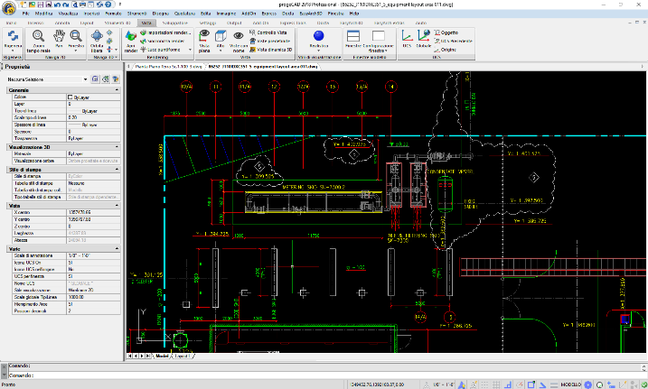
Ribbon and Classic GUI
progeCAD supports both common Menu interfaces: the Classic one based on the standard toolbar and the new up-to-date Ribbon- based menu as of Microsoft Office® or AutoCAD® Ribbons use tabs to expose different sets of controls, eliminating the need for many parallel toolbars. Customizable through CUI Files.Users accustomed to the classic Drop-Down menu and Toolbars can still stick to their preferred style.
Object Fade Control
Enhanced management of elements with automated fade control of objects on locked Layers and in external references (xref), as well as of non-editable elements in blocks.
EasyArch 3D - The Architectural 2D/3D plugin
The automated building tool for architects designed to increase productivity in house and interior design and remodelling.
EasyArch allows to: Create walls, Edit walls (delete, rotate, MOVE, copy, make/cap holes etc., Insert, copy, move, edit doors and windows automatically, Manage layers (quick turning on/off, freeze/unfreeze, isolate etc.), Manage and insert parametric blocks from the additional menu, Create stairs, Create roofs, Create and edit tables of elements, rooms, spaces, Assisted dimensioning

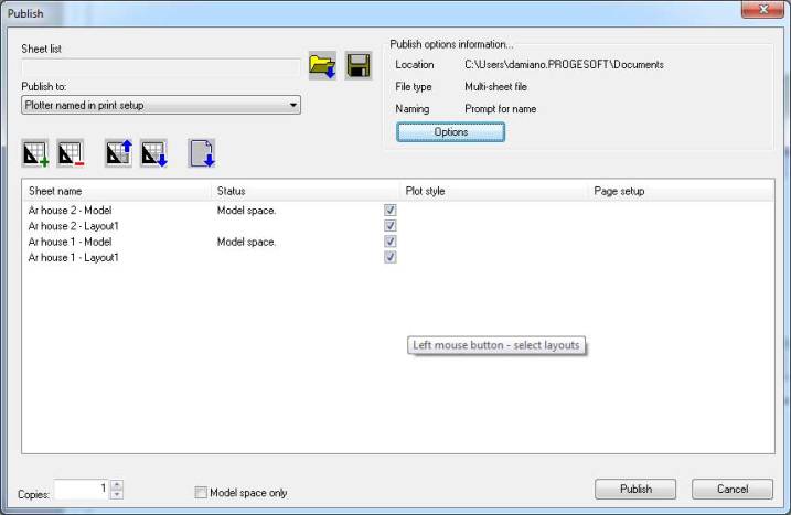
Publish (Batch Plot)
Layouts taken from one or more drawings can be printed or exported to PDF or DWF using the print settings of individual layouts Speed up the print process when necessary to print or export several different drawings or drawings with several different layouts.
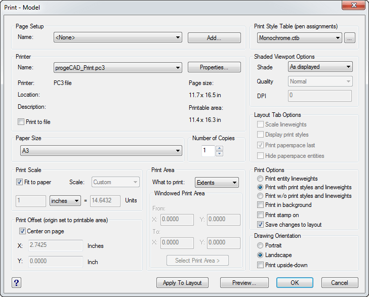
Plotter Configuration and PC3 support
Improved printer management with printer control better integrated with progeCAD, paper orientation control, Layouts configurations stored in the drawing. Starting from progeCAD 2013, configurations for Windows system printers are stored in plotter configuration files (.PC3 files). Unlike in AutoCAD, PC3 plotter configuration files in progeCAD apply to Windows system printers only. In a plotter configuration file, you override one or more settings of the Windows system printer installed on your system. You can configure progeCAD for many plotting/printing devices and keep multiple configurations for each single device.
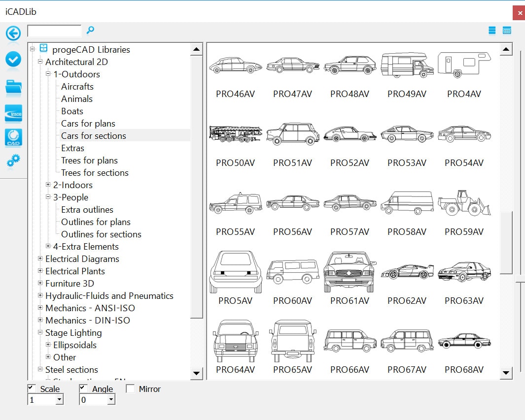
iCADLib module and Libraries
The advanced iCADLib module for blocks management ensures the best organization and management of your Symbol Libraries. More than 20.000 ready-to-use 2D/3D Blocks: Construction Architectural, ANSI-ISO and DIN-ISO Mechanics,ANSI and IEC Electrical, Electronic,Steel Profiles Furniture,Kitchen.
In-place Editor for Text and Multiline Text - NEW
New multiline text editor allows you to edit multiline text in place. However, not all multiline text features are implemented in the new editor. To switch to the older dialog box version of the multiline text editor, set the MTEXTED system variable to "oldeditor".
PDF, PDF/A and JPG format Printing/Export
ProgeCAD Professional automatically adds a virtual printer which can produce PDF files having no need of ADOBE ACROBAT. The PDF file parameters can be easily configured. progeCAD can create PDF files compliant with the PDF/A ISO19005 Standard. ProgeCAD also print drawings as Jpeg.
PDF Import (PDF2DWG)
ProgeCAD helps you convert your PDF files to editable DWG files quickly and easily. The PDF to CAD feature allows to save time by easily transferring projects, drawings, parts of existing in vectorial PDFs catalogues and manuals to CAD drawings to use them as native DWG files. Supports all versions of Adobe PDF file.
DWF/DWFx Import/conversion(DWF2DWG)
One click conversion DWF to DWG,DXF,DAE,3DS,DGN - Convert DWF to AutoCAD, 3D 3DStudio, SketchUP, Microstation
progeCAD convert DWF,DWFx files to different drawings file formats. Usable and editable quickly and easily.
The DWF2CAD feature allows to save time by easily transferring projects, drawings, parts of existing as DWF to CAD drawings to use them as native files. Convert DWF in 3 steps:
1) Install progeCAD 30-day Trial
2) Open DWF,DWFx files into progeCAD
3) Save as DWG/DXF or Export to DAE,3DS,DGN from the Export menu
Gradient Hatch Support
Gradients can be displayed and created through a user friendly interface. Improved Hatch Form.
ProgeCAD Cloud
Cloud services will reshape the consumer digital lifestyle experience, with progeCAD save and open drawings on Cloud! progeCAD Cloud makes it easy for you to reach any of your drawings wherever you are. progeCAD Cloud supports the major cloud services for file sharing and syncing like DropBox, Google Drive and Microsoft One Drive.

Traceparts and Cadenas for progeCAD
iCADLib integrates Traceparts web portal progeCAD's Cadenas web portal for easy guided usage of more than 100 million of blocks. TraceParts and Cadenas are leading digital engineering 3D content companies offering cutting-edge business solutions through powerful web based products and services.3D PDF Export
Create ADOBE PDF standard with your dynamic 3D content inside. PDF3D allows to communicate to all the globe and share your data with anyone in an easy and innovative way.
Perspective Image Correction
Thanks to the new plugin, images and photos insertion is easy and intuitive, with the ability to correct their perspective through the multi-point system.
Image georeferencing
Georeferencing is the process of scaling, rotating, translating and deskewing the image to match a particular size and position. Special for GIS!
ECW support
ECW is an open standard wavelet compression image format developed by Earth Resource Mapping. The file format is optimized for aerial and satellite imagery, and efficiently compresses very large images with fine, alternating contrast. This is a lossy compression format.MrSID support Multiresolution Seamless Image. It is a file format (filename extension .sid) developed and patented by LizardTech for encoding of georeferenced raster graphics, such as orthophotos. The MrSID (.sid) format is supported in major GIS applications such as Autodesk, Bentley Systems, CARIS, ENVI, ERDAS, ESRI, Intergraph, MapInfo, and QGIS.
Jpeg 2000 support
Jpeg 2000 is a wavelet-based image compression standard. It was created by the Joint Photographic Experts Group committee in the year 2000 with the intention of superseding their original discrete cosine transform-based JPEG standard.
PDF, DWF and DGN Underlay
PDF, DWF and DGN files can be attached as an underlay to a drawing file and used as background for your drawings. CAD entities can be created over the Underlays. Much like raster image files and external references (Xrefs) an underlay is not part of the drawing, but is linked to it.
Raster
Insert and manipulate Raster images with only one click of the mouse! With the powerful raster editing and raster-to-vector conversion tools, progeCAD helps you to easily clean up, edit, enhance, and maintain scanned drawings and plans. Use a wide range of image data, embed images, insert and export images and use a polygonal mask boundary to display image subsets. Image transformation functionality and georeferenced image display.
Raster to vector
progeCAD Professional includes WinTopo, the raster to vector tool, which main functions are:
- Loads BMP Bitmap images (raster)
- Refines bitmap lines and detects the edges
- Creates monochromatic vectors from refined lines
- Views vectors on top of the bitmap
- Load vectors to progeCAD, IntelliCAD, AutoCAD
ACIS Solids
Main functions: reads and writes 3D solid objects with ACIS libraries (the same as AutoCAD®). ACIS solids are available thanks to an agreement signed with Spatial, the supplier of technology for solid modelling to the most important CAD software in the world. progeCAD Professional has implemented a complete management of ACIS solids, which can now be viewed, printed, created and edited. Any exchange of projects with CAD, which include ACIS Solids (such as AutoCAD® 2000, 2009), is therefore much easier! Creation of complex three-dimensional shapes using solid models becomes a way simpler procedure.
Dynamic Input
Dynamic Input is an alternative way of entering commands through a command line interface at your Crosshair. You can input data like the length of a line or the radius of a circle with dynamic visualization of changes relative to mouse movements When dynamic input is turned on, a tooltip displays dynamically updated information next to the cursor. When a command is in progress, you can specify options and values in the tooltip text box. You can also configure dynamic input to meet your personal or company standards. The feature is to further boost your productivity by making drafting and editing processes way more efficient.
Dynamic UCS
The previous progeCAD versions constrained the drafter to constantly change the XY plane to work on a particular face or plane of an object when working with 3D models. You had to specify a new user coordinate system every time you changed views. The new dynamic UCS feature automatically creates a temporary XY plane to draw on. The dynamic UCS feature dramatically speeds up drawing in 3D environment.
MultiLINE
The multiline command allows the drawing of multiple parallel lines with a single command. Not only does this feature allow you to create simultaneous, perfectly parallel lines, but these lines are also treated as one entity allowing easier editing. The Multiline support greatly speeds up and simplifies drawing and improves the AutoCAD ® compatibility. Multilnes Styles supported.
Spiline Editing
You can delete fit points of a spline, add fit points for greater accuracy, or move fit points to alter the shape of a spline. You can open or close a spline and edit the spline start and end tangents. Spline direction is reversible. You can also change the tolerance of the spline. Tolerance refers to how closely the spline fits the set of fit points you specify. The lower the tolerance, the more closely the spline fits the points.
You can refine a spline by increasing the number of control points in one portion of the spline or by changing the weight of specific control points. Increasing the weight of a control point pulls the spline more towards that point. You can also refine a spline by changing its order. The spline order is the degree of the spline polynomial + 1. A cubic spline, for example, has order 4. The higher the spline order, the more control points it has.
Multigrip Editing
Modify, move, rotate, scale, stretch or mirror using multiple Grips
Advanced Solid Grips
By dragging grips you can change the shape and size of primitive solids. For example, the change of the height of a cone will maintain the overall cone shape and automatically update the base radius. The Solid Grips feature is introduced to enrich 3D editing operations. Snap Extension Snap to some point along the imaginary extension of a line, arc or a polyline segment
AEC objects visualization
Graphical entities created with Architectural Desktop are visualized inside a DWG drawing file
DGN Import
Import drawing files from Microstation Collada Import. Import Collada (.dae) drawings
STL and Collada (DAE) Export
COLLADA is a COLLA borative Design Activity for establishing an interchange file format for interactive 3D applications. Collada is supported by several 3D software like SketchUp®, SAP Visual Enterprise Author, 3DS Max etc.
STL (STereoLithography) is a file format native to the stereolithography CAD software. STL is also known as Standard Tessellation Language. This file format is supported by many other software packages; it is widely used for rapid prototyping (3D printers) and computer-aided manufacturing.
Render Export Tool
The export tool for Lightwave 3D (.lwo), 3DStudio (.3ds), Kerkythea (.3ds), Pov-Ray (.pov) makes progeCAD a friendly companion to export drawings to advanced rendering engines.
Default layers - NEW
Set up progeCAD with default layers to place automatically dimensions and tests on the correct layer.
Layer manager
Save different layer states (on, off, thawed, freeze etc.) for different editing, visualization or printing requirements and restore them in a click.
Express tools
Express tools is a library of more than 30 highly efficient tools designed to help you boost your progeCAD productivity. Easy-to-use, integrated into menus and toolbars, and cover a wide range of progeCAD functions, including layer management, drawing, object selection, object modification and extended data.
Quick dimension
Create and modify quickly a large number of dimensions at a time.
Dimension Style Manager
Creates new styles, sets the current style, modifies styles, sets overrides on the current style, and compares styles
Polygonal layout viewports
Create a nonrectangular layout viewport or convert a closed object, polyline, circle etc. into a viewport.
Annotative Objects
The feature automates the sizing of annotations such as text, hatch and dimensions in multiple viewports with varying scales.
The annotative objects are scaled based on the current annotation scale setting and are automatically displayed at the correct size. The following objects can be annotative, meaning that they can size automatically:
- Text (single-line text)
- Mtext (multi-line text)
- Dimensions
- Tolerances
- Hatches
- Blocks
- Block attributes
Find & replace
Automatically finds (or replaces) a string into a dwg drawing, supported in Texts, Attributes, Hyperlinks, Dimensions.
Loft Command
The loft command is similar to the extrude command, but much more versatile. Instead of extruding a single shape, the loft command allows you to extrude several shapes and make one continuous object.
FlatShot
Creates a 2D representation of a 3D solid object based on the current view of the solid object. An entire drawing can be flattened with an single operation.
Helix Command
Draws a 3D Polyline in the form of a helix
DWF import & export
progeCAD Professional reads and writes standard DWF files. DWF Export supported.
DWF View
progeCAD Professional visualizes DWF files.
Recovery manager
An easy drawing recovery through the graphic interface in case of crashes.
Realtime pan & zoom
The exclusive PPAN Technology* provides pan and zoom in realtime allowing easy management of large drawings, also with big hatches and TrueType fonts.
Polar tracking (Polar snap)
It helps to draw objects at specific angles or in specific relationship to other objects. When polar tracking is turned on, temporary alignment paths help you create objects at precise angles.
Eattedit
Advanced attribute editing, the AutoCAD® like feature.
Etrack - Otrack
Used to avoid the necessity of drawing construction lines in order to locate points.
Xref manager
progeCAD manages insertion of external references into the drawing, that means that other drawings are dynamically inserted in the main drawing Modifying a secondary drawing, the corresponding drawing inserted in the original one will also be modified. The Xref manager is an integrated mask (similar to the one available in AutoCAD ) which allows management of external references insertion easily and visually.
eTransmit
Utility for gathering, compacting and transmitting DWG files. External references (xref) , fonts, shape files, images and other supporting documents are included in the eTransmit pack, improving drawings interchange.
Flexibility and personalization
Like AutoCAD®, progeCAD has a bar for typing commands and a series of icons arranged around the drawing area which facilitate and speed up the use of various functions. There are obviously pull-down menus which, like command aliases and tool bars, can be personalized. Likewise the management of layout and blocks is compatible with AutoCAD®. Layouts and blocks can be managed and inserted with the help of the same commands as in AutoCAD®.
Development (AutoLISP, IRX, SDS, VBA, .NET)
The user can choose between different programming languages in order to personalize progeCAD (C#, VB.NET, VB, Delphi, Lisp, C++ etc.). As well as LISP, IRX C++ similar to AutoCAD® ARX, SDS C++ compatible with AutoCAD® ADS, Microsoft's Visual Basic for Application (VBA), COM automation support, .NET support